 Presents:
How to build an anodizer for chump change
- Anodized titanium coloring is based on the voltage controlled thickness of a dielectric (electrical insulator) oxide layer.
You need a controllable voltage source from about 20-130vdc able to provide the desired current
(100ma is sufficient for small areas. Even large, if you have patience and a current limiter).
Visit my page explaining the natural law covering how titanium is colored without ink, dye, or paint. - Aluminum coloring is a current-based anodizing and dying process. It requires a low voltage source (typically 6-12vdc, like a battery charger).
Here's a good how-to page on how to anodize aluminum.
Here's another good resource for anodizing aluminum.
This article assumes that you want to build a regulated, controllable
Direct Current voltage source
specifically for anodizing reactive metals such as titanium,
niobium (columbium), or tantalum to create the refracted, photonic interference colors.
With a tool like this, and the know-how presented in my
how to anodize page, you can make stuff like what I make.
To buy a ready made anodizer for reactive metals (Ti, Nb, Ta), try ReactiveMetals.com for a studio anodizer unit for about $203.00
See a picture of some other units on my Anodizer Example Page.
Basic parts:
| Function | Traditional Component | Details / est. price | Discount component | Details / Price |
|---|---|---|---|---|
| Safety | Isolation Transformer | 4 amp 12 lb $150 | GFCI Outlet | 15 amp $8 |
| Voltage Control | Variable Transformer | 5 amp+ 10 lb $70-$250 |
Dimmer switch | 6 amp $4 |
| Rectifier | Diode Bridge rectifier | 10 amp $3 -$6 | Diode Bridge rectifier | 10 amp $3 -$6 |
| Smoother | Electrolytic Capacitor | 1000 mfd, 150v $20 | Electrolytic Capacitor | 1000 mfd, 150v $20 |
| Fuse and holder | Fast acting | 10 amp $4 | Fast acting | 10 amp $4 |
| Cap Drain | Power resistor | 200w 100 ohm $8 | Light bulb & socket | $3 |
| Current limiter | Power resistor | 200w 100 ohm $8 | Light bulb & socket | $3 |
| Voltmeter | Panel Meter | 150 vdc $25.00 | Multimeter | 150 vdc $5.00 |
| Switches | Toggle switches | 15 amp, $2.50 each | Light switches | $0.40 each |
| Wire, electrical tape, wire nuts, pigtail, etc. |
< $10 | < $10 | ||
| Approx. Total: | $300+ | < $50 |
Warning: Any anodizer is a high-voltage source capable of
electrocuting you. Whether or not you build it yourself, be sure you understand
all the necessary safety procedures. These instructions are intended for (at
minimum) competent tinkers and handymen. Ideally, an electronics hobbyist or
electrician should be consulted or involved.
The parts list is intentionally vague: I've built most of my anodizers even
cheaper than listed by shopping electronics salvage houses, and understanding
the range of substitutions available.
Note: The following instructions assume the cheapest route of using the GFCI outlet and Dimmer switch. Wiring is slightly different using a variable transformer ("Variac"). But the (barely useable) dimmer can be replaced with a stable variac later, saving most of the other components.
FYI: The dimmer and light-bulb route is fine for playing around. If you want a truly functional, steady, stable and long-lived unit, spend a little bit extra for a variable transformer and power-resistors.
Step 1: You must be comfortable working with high voltages, and confident that you can build a safe device. If you aren't, pass these instructions to a friend who is.
Step 2: Shop for parts. Most of these parts are available at hardware stores (such as Home Depot, or Lowe's) and (after the demise of Radio Shack) eBay is useful for weird components like rectifiers, power resistors, and variable transformers.
Step 3: Put the parts together in the order indicated in the illustration below. Use connectors, wire-nuts, solder, or whatever is appropriate for the components and case that you end up using.
Note: The lines in the drawing are not exactly representative of the locations on the
components the wires will necessarily connect. Components (such as GFCI outlets and recifiers)
may have different physical layouts. The text notes take priority over the crude illustration.
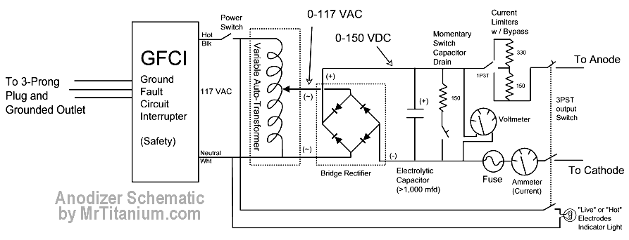
See the schematic below for a more precise and better design.
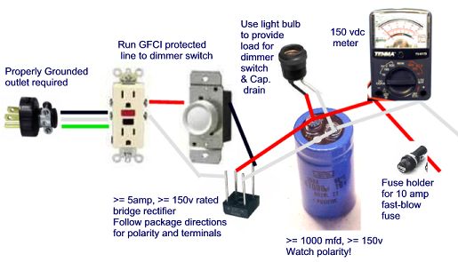
This illustration shows basically how the essential parts fit together. Be aware of grounding and polarity wherever either applies. If you don't know what I'm talking about, don't build your own.
Click here to see and read about the whole construction process as I built this type of anodizer.
Mount all possible components in a box, chassis, or to a board for stability, and insulate all exposed contacts and connections in appropriate manners.
The component list above mentions a current limiter, which is not shown in the illustration. Just put another light bulb (7 watt or so) between the meter and the fuse to allow slow anodizing. A switch across that lamp would allow you to easily limit and un-limit the current.
Also not shown is an Ammeter, which is necessary to display the current in order to electroplate, or electro-etch.
Put the parts in a container for safety. You may be able to fit the GFCI, dimmer, and other small electronics into a standard residential wall box, let the light bulb hang out, and cover the capacitor contacts with electrical tape. You could buy or build a metal box enclosure. I built my first Jerry-rigged dimmer-based anodizer in a box of masonite perf-board. I do not recommend this practice unless your really understand where the heat comes from and will go. Use non-flammable materials for mounting components.
Peculiarities of this discount circuit:
- The dimmer switch usually has to be turned up to over 35 volts to get the circuit to start up, but then can be dialed back to get voltages as low as 10.
- At low voltage settings: Sudden drops in house voltage, such as an air-conditioner, dehumidifier, blower, or refrigerator coming on, may cause the circuit to turn off. Just turn it back up over 35v or so till it turns on, and then back down to where you need it.
- The dimmer circuit is very sensitive to your line voltage, which normally will vary by 10% or so depending on time of day, and by what else is connected and running between the transformer and your anodizer. This is because the dimmer switch uses a triac (sort of an AC transistor), which basically turns off the voltage when the normal sine wave of the AC current reaches a given proportion of it's peak. It is non linear, and is most picky in the middle of the range (about 75 volts). You definitely need a voltmeter to get reproducible results
- One reader suggested a way to manage the voltage sensitivity using a power-converter
such as a high-end computer backup power supply. Make sure you get the kind with continuous
conversion. I.E: One that converts
all power to 12vdc at the battery and then inverts it back to 115vac.
But, it may be simpler and cheaper to use a variable transformer (e.g: Variac®) instead of a dimmer switch and eliminate the whole sensitivity and drop-outs problem.
You still need the GFCI for protection - Play with light bulb sizes for the dimmer load. 60 watts is a good compromise. I've used from 7 to 100 watt bulbs, and they all work. The choice is between how much dimmer noise you can take at low voltages, vs. how much light/power you waste at high voltages.
- Keep a supply of fuses handy. You need the fuse to protect the capacitor
and rectifier from accidental shorts between your working anode and cathode.
Shorts happen!
The GFCI protects you from accidental grounding. Nothing protects you from touching both the plus and minus wires! Always be aware of where all parts of your body are in relation to the exposed parts of these wires.
A dead-man switch (normally open momentary, ideally DPST) between the voltmeter and the contacts is a good idea. A DPST switch will disconnect both leads when released.
Cautions (weasel words to protect me from liability for your potentially dangerous goofs):
- High voltages: A perfectly built anodizer is designed to deliver high voltages. Use with care!
- Grounding: If the circuit is not plugged into a grounded outlet, the GFCI protection won't help. Make sure that the outlet is properly grounded! If you don't know how, I recommend that you don't attempt this project.
The resistors need to be rated for serious power, like 150 ohm, 200 watt. Light bulbs are cheaper.
Click Here for a dimmer and lighbulb based schematic drawing.
Examples: I'm posting pictures and descriptions of anodizers built with the help of the info I provide. See them here
Topic: capacitor came in the mail!
1800 mfd, 350V caps, about the size of a 16oz beer can. :O
Anyway, I finished making my cheap 40 dollar 120VDC variable power supply with it, and I grabbed some titanium 1/16th ID 24ga earrings I've been working on and stuck them in there. Very nice colours. This titanium anodizing stuff is really freaking cool."
Fortuna Wolf (Jan 29, 2003)
Once again: To buy a ready made anodizer, try
 for a studio anodizer unit delivered for under $500. I haven't found a better deal.