 Presents
Samples of home made anodizers
Anodizers shown here were made by people who took some inspiration or guidance from my "Make an Anodizer" page.
There are 6 home-made anodizers featured on this page as of October 2014
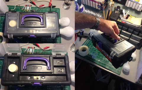
(October 2014) Adam sent me a link to his album detailing how he built a portable dimmer-based anodizer in a tool box. Note the clever use of top compartments to hide the switches, contacts, and knob. |
|
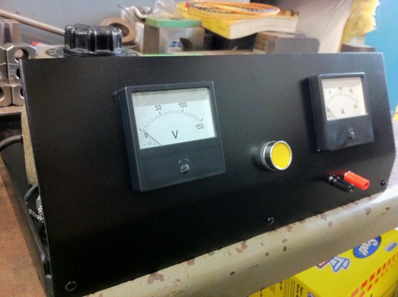
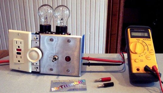
In 2013 Joe wrote:
I used your instructions to build this. Thanks you for all your time and effort in putting together your very informative website. I put this together for a bit less than $100. I fabricated the frame and front panel and then CNC machined the heat sink for the rectifier. Everything else I bought from eBay or Allied electrical.
I recently started making bicycle racing parts out of 6al 4v and wanted to be able to anodize them.
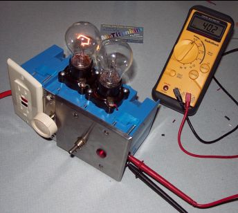
(July 2003) Fixer-of-Things, a chain mail artisan (www.we3dements.com) posted a description of his anodizers on a BBS, including one made by my instructions. I copied it with his permission. |
|
(May 2003) Oberon the SteelWeaver is selling this model from his web site at www.steelweaver.com I assume that there are internal power resistors instead of the lightbulbs I used in my Make an Anodizer" page and below |
|
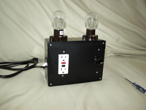
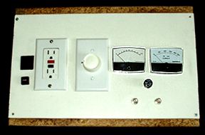
(Early May 2003) This one I made myself roughly according to my own instructions.
Click here to see and read about the whole construction process
to make this roughly competent anodizer.
(Dimmer-based anodizers are a little flaky in the
low voltage range (<= 30v, Blues, violets, tan))
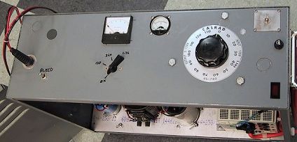 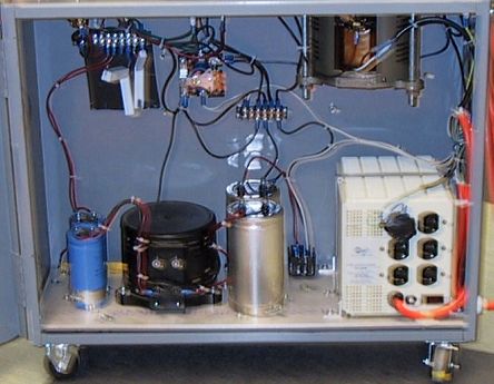 |
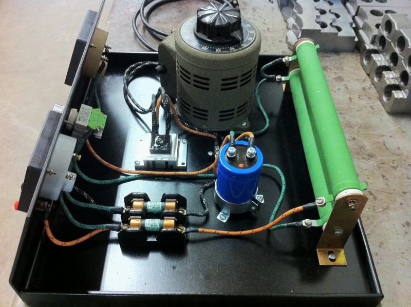
Here is one ambitious anodizer mostly made from scrounged parts and nicely mounted in a case. Power comes in through a salvaged computer power regulator (bottom rt) that isolates (safety), smooths, and regulates the AC voltage. The juice then passes through the variable transformer mounted to the top, and then is turned to DC by the bridge rectifier, held by a heat sink seen on the bottom between the silver capacitors and the power regulator. The bottom left has a fancy array of capacitors and a large ferrite-core choke (a cast-off, slightly burned (formerly variable) transformer) to provide r-e-a-l-l-y smooth DC. Overkill, imho. The rest of what you see are switches, relays, meters, and resistors to provide control and safety. And casters for portability He told me that he spent a total of $130.00 on parts for this heavy-duty, ultra-smooth performance unit. The input regulator and (overkill) choke were straight salvage. |